Resources
AI workloads are forcing data center (DC) operators to rethink the fundamentals of facility design. GPU-dense clusters create concentrated power draw, reject far more heat per node, and push airflow systems beyond what conventional layouts were built to handle. Facilities engineered in the mid-2010s for 5–10 kW racks now strain under the 30–100 kW densities common in large-scale training and inference.
NVIDIA's AI factory concept—purpose-built facilities designed around GPU-dense clusters—treats these power densities as baseline, with next-generation architectures like GB200 NVL72 pushing toward 120 kW per rack.
These pressures have shifted the design focus from incremental optimization to grid-to-rack engineering. Hardware that draws several times more power than legacy servers and depends on liquid cooling requires new electrical and thermal paths rather than retrofits.
The new generation of AI-ready facilities starts with physics. Power delivery efficiency and thermal management now define computational performance as much as the GPUs themselves. Modern designs employ medium-voltage distribution to minimize transmission losses, 48V rack-level conversion for improved efficiency, and direct liquid cooling to handle heat densities that would overwhelm traditional air systems.
These aren't optional upgrades; inefficient power delivery and inadequate cooling directly translate to higher costs per token and slower model convergence. Building an AI-ready data center means aligning the entire environment—power, cooling, and layout—with the realities of accelerated compute.
Design principles: what “AI-ready” really means
Designing a facility for AI compute starts with the simple premise that training throughput is the priority metric. Every subsystem (electrical, thermal, mechanical) either preserves or erodes it. An AI-ready hall is one where power and cooling never become the bottleneck.
Throughput as the constraint: Large training runs are highly sensitive to small fluctuations in the hardware supporting them. A minor voltage sag, a small rise in coolant temperature, or a few seconds of pump instability all increase tail latency at scale. When GPUs hit thermal or power limits, they don't fail; they throttle, slowing down performance. Facilities have to be engineered to be resilient to faults at all levels, and transient events must not impact performance.
Thermal limits define hardware limits: Legacy data centers were built around 5–10 kW racks; AI clusters now routinely push 30–80 kW, with 100–150 kW per rack already shipping as productized targets. Modern rack-scale liquid-cooled solutions are now specified to handle up to 100kW per rack, with some vendors already demonstrating 150kW and above configurations.
At these densities, the heat flux simply outruns air. Air systems still shape the boundary conditions, but liquid cold plates become the primary thermal path. Rising processor TDPs make this shift inevitable, as without direct-to-chip cooling, facilities reach diminishing returns where fans consume exponentially more power for marginal cooling gains, while the chips themselves leak more current and waste more energy as temperatures rise.
When GPUs exceed their designed operating temperatures, they automatically reduce clock speeds to protect themselves, which is immediately reflected in longer convergence times and higher cost per token.
Serviceability without disruption: High-density liquid-cooled racks must be serviceable without coolant drainage or compute interruptions. Modern cold plate deployments rely on quick-disconnect couplings — connectors that separate without leaking — and rear-of-rack manifolds that distribute coolant to individual servers.
That said, component quality varies widely across vendors—quick-disconnect reliability, cold plate thermal performance, and manifold durability all differ enough to affect long-term serviceability. That's why our infrastructure partnerships prioritize vendors with proven high-density deployments, because the operational costs of unreliable components far exceed any savings at procurement.
These designs let operators isolate and service a single node without draining the entire cooling loop or affecting neighboring hardware. This approach has become the industry standard for maintaining high-density racks in production.
To turn maintenance into a hot-swap operation rather than a disruptive event, physical design is key. Front-accessible components where rack geometry allows—liquid manifolds often route to the rear to avoid cable conflicts—precisely planned cable management to keep pathways clear, and strategically placed isolation valves.
Modularity as a reliability tool: Modern AI deployments are organized into pods, which are often designed to be bounded units of racks, power, and cooling that act as scaling increments. Vendor architectures now formalize this with scalable units that can be added, isolated, or serviced as discrete blocks.
Industry reference designs and data center guidance treat these modular blocks as a practical way to contain the impact of faults while simplifying phased rollouts. Done well, this keeps localized problems and maintenance work from affecting neighboring pods.
For inference workloads, container orchestrators like Kubernetes can autoscale around failures with minimal disruption. Training is less forgiving, as any node failure forces a rollback to the last checkpoint and workload migration. Emerging orchestration platforms are beginning to address training resilience more intelligently, but robust infrastructure remains the primary defense.
Before deploying production hardware, facilities must pass integrated testing that simulates actual training workloads. This means running real power draws, thermal loads, and network patterns, not just checking against rated capacities. Typical acceptance suites start with CPU/GPU burn-in for 24–48 hours to verify hardware health, then move to performance validation: NCCL for network throughput, HPL for GPU compute, and storage I/O testing across a range of read/write workloads using both small and large files to confirm the system meets design specifications.
Commissioning teams now require full-stack validation under realistic stress, with power, cooling, controls, and orchestration running concurrently before certifying a facility for AI workloads. These core principles of throughput, thermal management, maintainability, and modularity then guide every implementation detail, from selecting medium-voltage equipment to routing coolant manifolds.
Power architecture: From utility to GPU
The power chain in an AI-ready data center must handle both the massive scale and the dynamic nature of modern training workloads. Unlike traditional IT loads, which remain relatively steady, AI clusters can swing from idle to peak power in milliseconds, creating electrical transients that propagate from the GPU back to the utility feed. Every conversion stage, protection device, and distribution path must be engineered to absorb these swings without voltage sags, harmonic distortion, or cascading failures.
Medium voltage design for resilience and flexibility:
Modern AI facilities start with medium voltage (MV) distribution at 12.47 kV or 24.9 kV, reducing transmission losses and cable sizes compared to low-voltage feeds. The architecture typically employs dual utility feeds from separate substations, or a utility feed paired with on-site generation: either natural gas turbines or, increasingly, battery energy storage systems (BESS) for shorter-duration backup.
The challenge with island-mode operation for AI workloads is that training algorithms execute synchronously across GPUs, creating oscillating load profiles that can destabilize generators not designed for such rapid transients. Modern facilities address this with synchronous condensers, flywheel systems, or an inline UPS that provides a sub-millisecond response to load steps, acting as shock absorbers between the power plant and the compute load.
The MV switchgear includes automatic transfer switches (ATS) with closed-transition capability, allowing seamless transfers between sources without interrupting compute. From the MV level, transformers step down to 480V for distribution to IT halls, with some facilities now exploring direct 480V-to-48VDC conversion to eliminate an entire conversion stage.
48V distribution cuts losses and copper:
The shift from 12V to 48V rack-level distribution reduces current by 4x at the same power delivery, cutting distribution losses by 16x since losses scale with the square of current. This becomes critical at AI densities where racks pull 100+ kW — at 12V, a single rack would require over 8,000 amps, making cable sizing and connector reliability nearly impossible.
Industry momentum is clearly toward 48VDC at the rack, with future architectures likely to push toward even higher-voltage DC distribution to further reduce conversion stages and losses.
Google reported a 30% reduction in conversion losses and a 16x reduction in distribution losses when moving to 48V architectures with direct point-of-load conversion. The 48V bus powers the power shelves in each rack, which then convert directly to the voltages required by GPUs (typically 0.8-1.2V) using high-efficiency voltage regulator modules (VRMs). Modern switched-capacitor converters achieve over 98% efficiency for the 48V-to-12V intermediate conversion when required for legacy components.
Busways rated for 400-600A at 48VDC run overhead or under raised floors, with tap boxes every few meters to feed rack power shelves. In some high-density deployments, these busways use laminated copper bars with integrated cooling channels. Redundant power shelves in each rack provide N+1 redundancy at the point of use, eliminating single points of failure.
 Source: Article
Selective UPS strategies for AI workloads:
AI training creates dramatic power fluctuations as GPUs synchronize their operations, requiring UPS systems that can handle load swings of 50% or more in milliseconds without triggering protection circuits. Rather than protecting the entire facility with UPS, selective deployment focuses battery backup on critical subsystems**.**
For us, requirements vary by client, but at minimum, this typically covers storage, core networking, out-of-band management infrastructure, CDUs, and rear-door heat exchangers—the systems that preserve job state and prevent thermal runaway if power fluctuates.
The control plane, including job schedulers, network controllers, and storage metadata servers, receives complete UPS protection with runtime targets of 10-15 minutes. These systems must stay online to preserve job state and enable orderly shutdown if needed. Compute nodes often rely on "UPS-lite" configurations: capacitor banks or small lithium-ion modules that provide just 30-60 seconds of ride-through, enough to handle utility transfers or brief sags but not extended outages.
Modern AI-tolerant UPS systems use lithium-ion batteries that handle high-frequency charge/discharge cycles better than traditional VRLA batteries, which struggle with rapid load changes above 110% rated capacity. The UPS includes predictive controls that anticipate load ramps based on job-scheduler signals and pre-position inverters to minimize voltage deviation during transitions.
Grounding and bonding for liquid-cooled systems:
Liquid cooling introduces new grounding challenges, as conductive coolants create potential paths for electrical faults. The facility requires a comprehensive mesh bonding network (MESH-BN) that bonds all metallic components, including liquid manifolds, cold plates, and piping, to a standard ground reference.
TIA-942 specifies that computer room grounding should begin with a signal reference grid (SRG) of #6 AWG copper installed beneath raised floors or above ceilings, with equipment racks bonded to this grid to minimize ground loops and electromagnetic interference. Liquid cooling components require additional considerations:
- All metallic pipes and manifolds must be bonded to the SRG using flexible copper straps that accommodate thermal expansion
- Isolation transformers for pumps and CDUs prevent ground loops between the cooling system and IT equipment
- Dielectric unions at rack connections prevent galvanic corrosion while maintaining safety grounding through parallel conductors.
The isolated ground system for sensitive electronics connects to the building ground at only a single point, using the highest-impedance conductor allowed by code to minimize noise coupling while maintaining safety. Ground impedance must be kept below 5 ohms, with 1 ohm or less preferred for facilities with extensive liquid cooling.
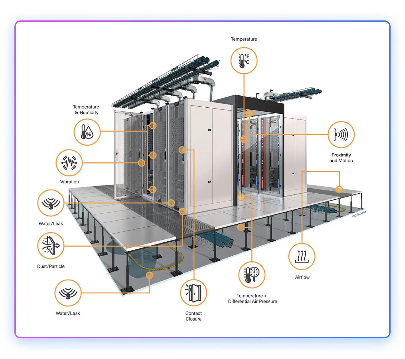
Leakage detection integrated with power control:
Modern leak detection systems use sensing cables that can detect both water and glycol-based coolants, with location accuracy within 1 meter along runs that can extend hundreds of feet. These cables use conductive polymers that change resistance when exposed to liquid, allowing the monitoring system to pinpoint leak locations.
The leak detection system interfaces with the emergency power off (EPO) logic via the building management system (BMS), but confirmation matters more than speed. Strip-style sensing cables are prone to false alarms from condensation, humidity shifts, or residual moisture from maintenance, so robust designs require multi-sensor confirmation before escalating responses. Upon confirmed detection, the BMS can automatically close solenoid valves toisolate affected cooling zones and reduce IT load in impacted racks through server management interfaces.
Selective EPO for specific rack zones remains an option, but automatic EPO triggers should be approached with caution—an unnecessary power cut to a running training cluster often causes more damage than a contained leak.
Detection zones are hierarchical, with responses calibrated to confirmed severity:
- Rack-level sensors trigger local valve isolation and server throttling after secondary confirmation
- Row-level detection initiates cooling zone isolation and load migration
- Room-level detection can trigger full EPO, but typically requires operator confirmation unless the leak directly threatens electrical infrastructure
Liquid-cooling implementations require special attention to routing, with codes increasingly prohibiting coolant pipes from passing through electrical rooms, even with drip trays, requiring alternative routing paths that add complexity but reduce the risk of catastrophic failure.
The integration between leak detection, power systems, and cooling controls must be tested regularly. Monthly drip tests verify sensor sensitivity, quarterly valve actuations confirm isolation capability, and annual integrated tests validate the complete EPO sequence, including selective shutdown based on leak location and severity where required.
Rack layout & density: airflow, cable plant, and human factors
Even in predominantly liquid-cooled deployments, air remains the boundary condition. GPUs reject heat to cold plates, but power supplies, NICs, storage, and switch ASICs still rely on forced air cooling. The facility must manage both thermal paths without creating conflicts—liquid manifolds that block airflow channels, or hot exhaust recirculating into intake zones.
Front-to-back airflow discipline with hybrid cooling:
Modern AI racks employ hybrid thermal architectures: direct-to-chip liquid cooling handles 70-80% of the heat load from GPUs and memory, while forced air removes the remaining 20-30% from ancillary components. This requires maintaining traditional front-to-back airflow even as liquid manifolds occupy rear-of-rack space.
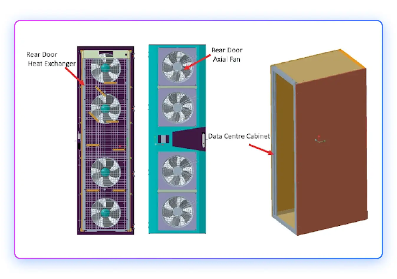
Facilities typically choose between hot-aisle containment and rear-door heat exchangers (RDHx)—combining the two is uncommon. Either approach must integrate with manifold assemblies without creating bypass paths.
The critical failure mode is hot-aisle bleed: when containment seals degrade, or manifold penetrations aren't properly gasketed, exhaust air mixes with intake air, raising inlet temperatures. A 3-5°C rise in inlet temperature propagates directly to GPU baseplate temperatures, which can push chips into thermal throttling even when liquid cooling is functioning perfectly.
Facilities use computational fluid dynamics (CFD) validation during design, then verify with thermal mapping during commissioning—infrared surveys at server intakes to confirm temperature uniformity across the rack face. Real-time thermal monitoring at the node level validates that service operations don't affect neighboring hardware—temperature drift on adjacent cold plates during a swap indicates inadequate isolation.
 Source Article
Cable management as operational infrastructure:
High-density racks generate three distinct cable plants: power (48V busbars or heavy-gauge DC feeds), networking (100GbE or 400GbE copper/fiber), and liquid connections (supply/return manifolds with quick-disconnects). Managing these without creating service impediments requires deliberate routing discipline.
Modern deployments standardize on:
- Overhead cable tray, underfloor routing, or trench space for power distribution—keeping primary pathways clear for liquid piping and allowing gravity drainage of any leaks away from electrical systems
- Top-of-rack (ToR) fiber staging with pre-terminated trunk cables and modular cassettes that allow port reconfigurations without re-pulling individual strands
- Under-floor or side-of-rack liquid manifolds with vertical risers to each server, using flexible hoses with reinforced strain relief at connection points
The patching topology matters operationally. Spine-leaf architectures with ToR switches create local patch zones. While reconfigurations on large-scale clusters are rare, necessary interventions, such as replacing failed cabling or transceivers, happen at the rack level rather than requiring runs back to aggregation points. Patching strategies vary by installation, but best-practice provisions reserve cabling capacity from the outset. This ensures a single failure doesn't require running new cables—an operation that risks disturbing adjacent fibre bundles and causing secondary failures.
Cable routing must preserve minimum service clearances where possible: 1.2m in front of racks for component access, 1.0m behind for manifold service, with aisle widths accommodating server rail extension without blocking adjacent access. These are ideal targets, though not always practicable in dense deployments. Facilities that undersize aisles create cascading delays—one rack's maintenance blocks neighboring racks, serializing what should be parallel service operations.
Maintenance envelopes for rapid node replacement:
Traditional data centers treated node replacement as a disruptive event: drain cooling loops, power down rack segments, physically extract failed hardware, reverse the process. AI training workloads running synchronized distributed operations cannot tolerate these delays.
Modern liquid-cooled rack designs enable hot-swap maintenance through several key mechanisms:
Quick-disconnect (QD) couplings at every server allow individual nodes to be isolated without draining the rack manifold. Industrial-grade QDs use spring-loaded seals that couple/decouple in seconds with < 1mL spillage, meeting IP67 sealing standards. These aren't optional connectors—they're the critical component that determines whether maintenance extends for hours or minutes.
Drawer-style server chassis with front-accessible components and rear liquid connections. Technicians release mechanical latches, disconnect QDs at the rear, and slide the server forward on rails. The entire sequence—from identifying the failed node to bringing replacement hardware online—aims to minimize time-to-repair for single-node swaps during production operations, though actual MTTR varies by GPU generation, failure mode, and OEM.
Redundant cooling loops at the rack level, with manifolds providing N+1 capacity. If a cold plate develops a leak or a QD fails, isolation valves isolate the failure to a single server position while the rack continues operating. This requires pressure sensors and flow meters at rack granularity, feeding into BMS controls that can automatically isolate faulted segments.
The operational test is simple: can a technician replace a failed GPU node during a multi-rack training run without impacting job completion time? If the answer is no—if the job must checkpoint and pause—the facility hasn't achieved true hot-swap capability, regardless of the hardware's rated features.
Water systems, heat reuse & sustainability
Liquid cooling shifts thermal management from air handling to water infrastructure, making the facility's water loop as critical as electrical distribution. At 100kW per rack, a 1,000-rack facility rejects 100MW of heat into water—requiring flow rates of 4,000-6,000 GPM through the primary cooling loop, depending on design ΔT.
Facility water loop architecture:
Modern AI facilities employ a two-stage cooling architecture: a primary loop using filtered, treated water (or water-glycol mixture) circulates through rack cold plates and rear-door heat exchangers, while a secondary loop transfers heat to outdoor cooling towers or dry coolers.
The primary loop operates as a closed system with stringent water quality requirements:
- Conductivity < 100 μS/cm to prevent galvanic corrosion in dissimilar metal connections
- pH maintained at 7.5-8.5 to minimize corrosion rates
- Particulate filtration to 5 microns to prevent cold plate channel fouling
- Dissolved oxygen < 0.5 ppm to reduce oxidation of copper and aluminum components
Coolant distribution units (CDUs) circulate primary-loop fluid, typically operating in warm-water mode up to ~45 °C supply (dew-point limited), with many deployments choosing ~30–40 °C to maximize chiller-less efficiency. Racks are often designed around a ~10–15 °C coolant ΔT to balance pump power and component temperatures, though higher ΔT can further reduce flow and energy if cold-plate and manifold design maintain good flow distribution and avoid chip hot spots. Facilities commonly specify ~15–20 LPM per rack at ~2–3 bar differential pressure, and CDUs are usually oversized ~20–25% to accommodate future rack density growth..
The secondary loop interfaces with outdoor cooling infrastructure—induced-draft cooling towers in humid climates, or hybrid fluid coolers in arid regions where water consumption matters. Free-cooling (using outdoor air to reject heat without mechanical chillers) becomes viable when ambient wet-bulb temperatures fall below the primary loop return temperature minus the heat exchanger approach temperature.
Leak detection integrated across facility systems:
Liquid cooling introduces the operational risk that legacy air-cooled facilities never faced: coolant escaping containment. Modern deployments treat leak detection not as an afterthought but as a critical safety layer integrated with power and thermal management.
Multi-layer detection topology:
- Point sensors at every rack-level manifold joint and server QD connection
- Sensing cables beneath raised floors along primary pipe runs, with zone isolation every 10-15 meters
- Drip pans with secondary containment under CDUs and major distribution headers
The detection system feeds into hierarchical response logic through the BMS:
- Rack-level leak → isolate affected server position, throttle IT load if thermal capacity degrades
- Row-level detection → close zone isolation valves, redistribute cooling to adjacent rows
- Room-level alert → evaluate EPO trigger based on proximity to electrical infrastructure
False positive suppression matters operationally. Condensation during seasonal transitions, residual moisture from commissioning, or humidity migration into cold zones can all trigger sensors. Detection systems now use dual-confirmation logic—both resistance change and optical sensing—before initiating automatic isolation, with manual override for maintenance scenarios.
Heat reuse and sustainability integration:
At 100MW thermal load, AI facilities become meaningful heat sources for district energy systems or industrial process heat consumers. Reusing waste heat improves facility economics and sustainability metrics, but requires careful integration with cooling system design.
District heating integration is most viable in cold climates with established infrastructure. Primary loop return temperatures of 50-60°C match well with low-temperature district heating networks. The facility acts as a heat source, selling thermal energy to offset cooling costs. Helsinki, Finland's data center strategy explicitly encourages heat reuse into municipal heating networks, with facilities achieving 40-60% heat recovery.
However, heat reuse limits the cooling system's flexibility. Higher loop temperatures reduce cooling efficiency when ambient conditions allow free cooling. Facilities must balance heat sales revenue against increased cooling energy consumption. Economic viability depends on local energy prices—cheap electricity and expensive heat create favorable conditions, while the reverse makes heat reuse financially marginal.
In practice, heat reuse programs are typically implemented at the data center provider level, with benefits flowing through as reduced facility operating costs rather than line-item credits visible to tenants.
Make-up water and treatment protocols:
Closed-loop primary systems still require make-up water to replace evaporation from secondary cooling towers (1-2% of circulation rate) and accommodate system leakage. Water treatment becomes critical for loop longevity:
- Pre-treatment: Deionization or reverse osmosis to achieve the target conductivity before initial fill
- Biocide dosing: Prevents bacterial growth in sumps and cooling tower basins, typically quaternary ammonium compounds at 15-30 ppm
- Corrosion inhibitors: Molybdate or nitrite-based compounds for ferrous metals, azoles for copper protection
- Side-stream filtration: Continuous 5-10% loop flow through bag filters to remove particulates generated by corrosion or biofilm.
Water quality monitoring occurs at multiple points—CDU supply, rack returns, and cooling tower basins—with automatic chemical dosing systems maintaining parameters within spec. Facilities typically budget for a complete primary loop changeout every 3-5 years as preventive maintenance, though well-maintained systems can operate longer.
Realistic PUE targets for liquid-cooled AI facilities:
Power Usage Effectiveness (PUE) has become the standard sustainability metric, calculated as total facility power divided by IT equipment power. Legacy data centers with air cooling typically achieve a PUE of 1.4-1.6. High-density liquid-cooled AI facilities can improve this, but not to the dramatic numbers sometimes claimed in marketing materials.
Realistic targets for modern AI facilities:
- Liquid-cooled with free cooling: PUE 1.15-1.25 in temperate climates, 1.25-1.35 in hot/humid regions. Facilities in extreme cold climates, like Iceland, can push below 1.10 with near-continuous free cooling.
- Hybrid liquid + air: PUE 1.20-1.30 depending on the ratio of direct-to-chip vs. air-cooled components
- Legacy air-cooled retrofits: PUE 1.35-1.50 due to oversized CRAC units and inefficient distribution
The efficiency gains come from eliminating CRAC units (which consume 15-25% of IT load in air-cooled facilities) and enabling higher free-cooling hours. However, liquid cooling introduces new parasitic loads: CDU pumps, control systems, and leak detection add 2-3% overhead. The net improvement is absolute but incremental, not the order-of-magnitude changes sometimes suggested.
Facilities pursuing aggressive PUE targets must balance efficiency with reliability. Running cooling systems at minimum capacity reduces overhead but eliminates thermal margin, leaving equipment vulnerable to failures or unexpected load spikes. Operators typically target PUE at 80-85% load rather than optimizing for peak efficiency at 100% utilization.