Resources
Data center power density is approaching a thermodynamic limit, with average rack power doubling to 17 kW in two years, yet AI training infrastructure operates in an entirely different tier. NVIDIA GB200 NVL72 systems draw 120–132 kW per rack, and next-generation architectures will exceed 240 kW. Traditional air cooling, built for 8–12 kW environments, cannot reject heat at this scale.
This thermal constraint dictates the design of all high-density AI clusters, directly impacting the physical infrastructure required for autonomous driving model training, humanoid robotics simulation, and wafer-scale inference. It also dictates where those clusters can be built. The global inventory of sites equipped with direct liquid cooling capability is severely constrained, and the speed at which new liquid-ready capacity can come online is itself a hard physical bottleneck. Cooling is no longer something that follows site selection — increasingly, it drives it.
The selected cooling architecture determines which GPUs an operator can deploy, the achievable compute density, and the sustained performance levels over the next hardware cycle. Miscalculating this thermal equation locks a facility out of the exact workloads that justify its capital expenditure.
The thermal wall
Air resists heat transfer — the same property that makes double-pane windows insulate a room — and water conducts heat roughly 25 times better than air at rest. In motion, the gap widens further: coolant flowing through copper microchannels in a cold plate removes heat approximately 300 times faster than a fan pushing air across the same chip surface.GPU power draw has climbed with each generation: the NVIDIA A100 drew 400 W per chip, the H100 pushed that to 700 W, the B200 hit 1,000 W, and Blackwell-generation chips like the GB300 reach up to 1.4 kW per unit. A single rack of GB200 NVL72 nodes now generates more heat than an entire row of general-purpose servers did five years ago.
The practical ceiling for conventional air cooling sits around 15 kW per rack, with rear-door heat exchangers (RDHx) pushing that to roughly 40–70 kW depending on the facility configuration. Below that range, advanced air-cooling methods remain viable. Above it, thermodynamics mandates liquid. There is no engineering workaround for this — it is physics.
Beyond roughly 40–60 kW per rack, cooling feasibility begins to dominate site selection, replacing land and the power grid as the core considerations. Once densities reach 80–100 kW, liquid cooling becomes mandatory, and site viability is determined solely by heat dissipation conditions and water resources.
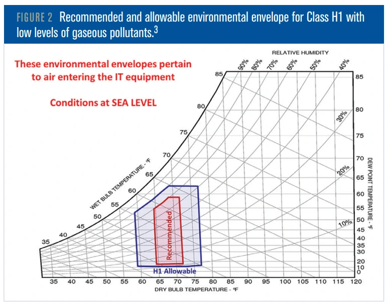
ASHRAE’s Technical Committee 9.9 acknowledged this reality by introducing the H1 environmental envelope, a classification specifically for high-density systems that require tighter temperature bands than traditional IT equipment.
The committee released a technical bulletin on liquid-cooling resilience in September 2024, followed by additional guidelines in January 2026 covering coolant distribution unit (CDU) design, transient modelling, and coolant quality monitoring. A new liquid-cooling thermal template is expected later this year.
The cooling architectures
Advanced air cooling with hybrid supplements, direct-to-chip liquid cooling, and full immersion in dielectric fluids are the three primary cooling architectures competing to address this bottleneck. Each serves a distinct density band and imposes rigid facility requirements.
Advanced air cooling: still useful, but bounded
Air cooling remains part of the thermal strategy in the majority of data centers worldwide, though the share running exclusively on air has dropped to 45%, down from 48% in 2024. For moderate-density deployments, retrofit scenarios, and edge inference, it remains the most cost-effective option.
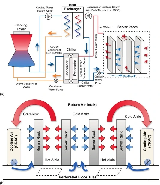
The improvements over the past decade have been meaningful. Hot and cold aisle containment eliminates the mixing of supply and exhaust air that previously wasted 30–40% of cooling capacity, while computational fluid dynamics (CFD) modeling allows operators to map airflow patterns and eliminate hotspots before they develop. Variable-frequency drives for fans and compressors further reduce energy waste under partial-load conditions.
Yet most air-cooled facilities still leave significant performance on the table. Research on AI-driven cooling optimization has shown that hot-air recirculation can raise inlet temperatures by 5–8°C and that bypass airflow exceeding 40% reduces cooling efficiency by more than 30%. The gap between a well-managed air-cooled hall and a poorly managed one is enormous — and too many operators are on the wrong side of it.
Rear-door heat exchangers represent the most significant extension of air cooling’s effective range. By mounting a liquid-to-air coil on the back of a rack, an RDHx captures exhaust heat before it enters the hot aisle, converting a purely air-cooled system into a hybrid. Meta’s Air-Assisted Liquid Cooling (AALC) deployments, for example, use rear-door heat exchangers to support up to 40 kW per rack, offering facilities that cannot justify a full liquid cooling retrofit a meaningful density upgrade with minimal infrastructure disruption.
At rack densities above 40–50 kW, even the best air-based systems cannot remove heat fast enough to prevent thermal throttling; the required volumetric flow rates become impractical, and fan energy alone begins to consume a disproportionate share of the facility’s power. For general-purpose compute, enterprise applications, and low-density inference clusters, advanced air cooling remains the right answer. For dense AI training clusters, it is not, and no amount of optimization will change that.
Direct-to-chip cooling: the production standard for AI racks
Direct-to-chip (DTC) cooling, also called cold plate or liquid-to-chip cooling, has become the default thermal management approach for current-generation AI infrastructure. NVIDIA recommended it as the standard thermal solution at the unveiling of the Blackwell architecture.
The technology itself is mature — products from all major system manufacturers now ship with direct liquid cooling, the result of a decade of engineering iteration that has successfully addressed the core challenge of placing liquid and electronics in close proximity.DTC systems capture 70–80% of a rack’s total heat via liquid cooling, with the remaining 20–30% generated by memory, storage, power distribution, and ancillary networking, which still require supplementary air cooling. This makes every current DTC deployment a hybrid system by design. Current GB200 NVL72 deployments typically run approximately 85% liquid and 15% air cooling.
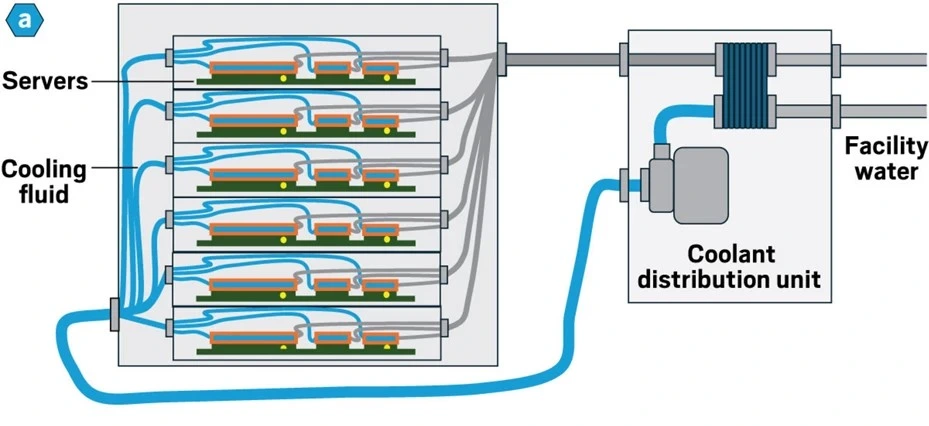
High-performance cold plates now achieve thermal resistances as low as 0.021°C/W, running chips 35°C cooler than air-cooled equivalents while supporting 60°C inlet temperatures. That temperature headroom translates directly to operational advantage. Cooler chips maintain higher clock speeds for longer, avoid thermal throttling during sustained training runs, and degrade more slowly over multi-year operational lifespans.
Single-phase split-flow DTC cold plates have demonstrated heat flux handling up to 200 W/cm² (sufficient for processors drawing up to 4 kW), while two-phase DTC approaches claim to reach 300 W/cm². NVIDIA’s Blackwell GPUs operate at 1.2–1.4 kW per chip, well within the capability of these cold plates, but as each silicon generation pushes higher, that headroom will tighten.
The infrastructure compatibility advantage of DTC is significant. Cold plates integrate with existing chilled-water infrastructure, deploy rack by rack without requiring facility-wide redesigns, and do not require purpose-built tanks or modified server form factors. For operators retrofitting existing facilities to support AI workloads, DTC is typically the lowest-friction path to high-density cooling.
ASHRAE’s liquid cooling guidelines define temperature classes for facility water supply ranging from W17 (17°C) to W45 (45°C) and above. Higher supply temperatures enable greater use of free cooling, reducing dependence on mechanical chillers, but as chip power densities continue to climb, operators are finding that supply temperatures need to drop back toward the W27 range to maintain adequate thermal margins. Facility designers now plan for this trajectory rather than optimizing exclusively for the latest GPUs.
Immersion cooling: the density frontier
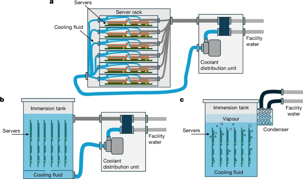
Immersion cooling eliminates the air path entirely by submerging servers in tanks of dielectric fluid that absorbs 100% of the generated heat, removing the need for fans and enabling rack-equivalent densities of 100–250+ kW.
Single-phase immersion
Single-phase immersion uses hydrocarbon-based dielectric fluids (mineral oils or synthetic poly-α-olefins) that remain liquid throughout the cooling cycle. Single-phase systems can support up to 200 kW per rack, achieve a partial PUE (pPUE) of 1.02–1.10, and use fluids that cost $50–100 per gallon.
A comprehensive review confirmed that single-phase immersion is effective for data centers with heat flux densities within its thermal range, while noting that the relatively lower thermal conductivity of current immersion coolants compared to water-based systems remains an active area of research.
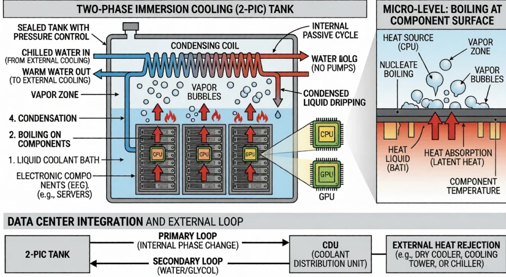
Two-phase immersion
Two-phase immersion uses a fluorinated refrigerant with a boiling point near 50°C that vaporizes upon contact with hot components, absorbing large amounts of energy during the phase change. This approach achieves the highest thermal efficiency of any current cooling method, with PUE values of 1.01–1.03.
Research has shown that two-phase cooling is effective for equipment with heat flux density greater than 1,000 W/cm², making it theoretically capable of handling anything the semiconductor industry can produce in the near term. Two-phase immersion faces a supply chain and regulatory problem that cannot be engineered around. The most effective fluids are per- and polyfluoroalkyl substances (PFAS), persistent synthetic chemicals facing tightening regulatory scrutiny in both the EU and the US, and the primary producer of fluorinated immersion fluids has exited production entirely. Replacement fluids exist, but at substantially higher cost and with less established performance data. A 40U rack-equivalent immersion tank costs approximately $20,000, with specialized low-boiling-point dielectric fluid adding another $15,000–$20,000.
A lifecycle assessment evaluating all major cooling approaches from raw material extraction through disposal found that liquid cooling methods reduce greenhouse gas emissions by 15–21%, energy demand by 15–20%, and water consumption by 31–52% compared to air cooling. The study also found that optimised cold plate or single-phase immersion systems can match the efficiency of two-phase immersion systems without the risk of PFAS exposure. Two-phase systems operate with coolant boiling at 50–100°C, producing reject heat that is high-grade enough for district heating, absorption chillers, or industrial process heat. Single-phase systems operating at lower temperatures still produce reject temperatures in the 40–60°C range, usable for building heating and preheating applications. In facilities where waste heat has economic value, immersion cooling can shift from a pure cost center to a partial revenue stream.
For new-build, high-density facilities, immersion cooling offers a density ceiling that no other approach can match. In 2025, Shell became the first immersion-fluid provider to receive chip manufacturer certification, with Intel providing a warranty rider for immersion-cooled chips and documenting electricity consumption reductions of up to 48%. But immersion requires purpose-built infrastructure — custom tanks, fanless server designs, specialized fluid handling, and facility layouts that differ fundamentally from conventional data center white space — making it a greenfield play rather than a retrofit.
Submerged hardware cannot be hot-swapped the way rack-mounted servers can. Servicing a failed component involves extracting it from a fluid bath, allowing it to drain, and managing the displaced fluid. For hyperscale operators running large homogeneous clusters where individual node failures are absorbed by the orchestration layer, this is manageable.
For operators running heterogeneous or smaller clusters where every node matters, the maintenance overhead is a real cost that should be modeled alongside PUE gains. Immersion cooling remains relatively customized, and large-scale application experience is still insufficient to call the operational model mature.
What the industry gets wrong
Two systemic problems sit underneath the technology choices, and the industry has been slow to confront either of them honestly.
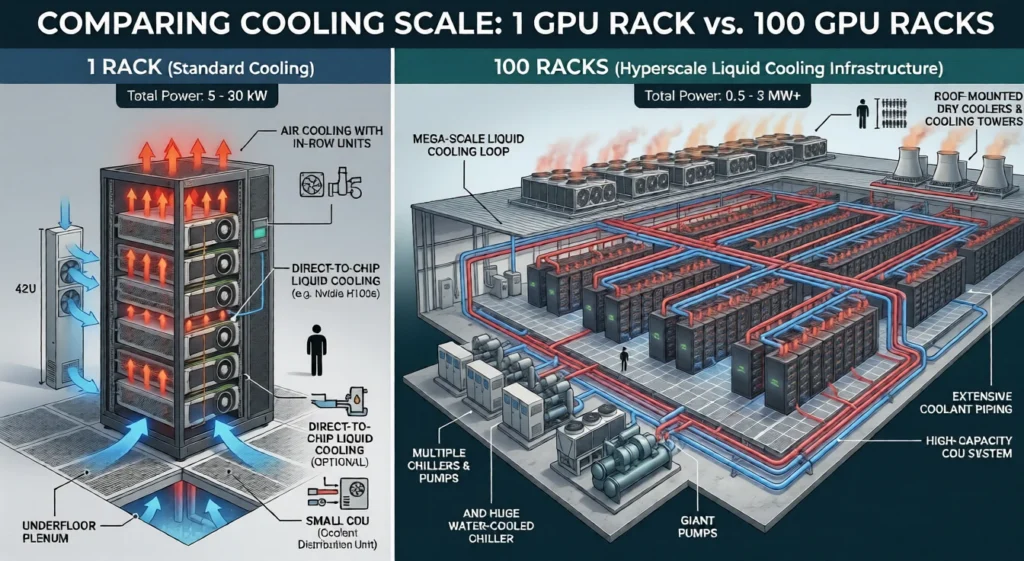
The one-rack-versus-hundreds problem
Where the industry’s confidence often outpaces its operational reality is at scale. Deploying a single liquid-cooled rack is a solved engineering problem with known solutions. Operating hundreds of them across a campus — managing peak demand, strategic cluster placement, and fault isolation — is an operational problem the industry is still working through in real time.
The unresolved issues are specific and consequential. Multi-vendor equipment remains severely incompatible, with no unified standards for design, construction, acceptance, or decommissioning. Long-term water quality control, anti-corrosion, and anti-scaling systems are imperfect. And fault isolation is difficult: when something goes wrong in a liquid loop, the problem does not stay local — it propagates. A leak or contamination event in one segment can cascade across racks before the source is identified.
These are active engineering challenges that every operator scaling liquid-cooled infrastructure is navigating today, and they deserve more honest discussion than the industry typically offers. The fact that the technology works at a single-rack scale does not mean the operational model for campus-scale deployment is settled.
The metrics problem
Most operators are still evaluating cooling performance through metrics designed for a fundamentally different era of compute.
PUE was born from a world of uniform compute density where you could measure facility efficiency through a single lens. At AI-scale densities, it becomes actively misleading. PUE does not reflect power density. It performs well at full load and conceals inefficiency at partial load, which matters enormously in phased AI deployment scenarios where facilities ramp over months or years. It tells you nothing about water consumption, space utilization, or whether your GPUs are actually sustaining their rated clock speeds under load. A facility with an excellent PUE number can still be thermally throttling its most expensive hardware.
Total cost of ownership modeling for cooling should extend beyond PUE and capital costs to include fluid replacement cycles, CDU maintenance intervals, leak-detection infrastructure, and the operational costs of maintaining specialized skills in-house or contracting them out. A system with a PUE of 1.03 that requires quarterly fluid testing and annual CDU overhauls may cost more over a five-year lifecycle than a system with a PUE of 1.10 and a lower maintenance burden. The right answer depends on the operator’s scale, in-house capabilities, and how long they plan to operate the facility at current density levels.
The industry needs to move toward metrics that capture what actually matters in high-density AI environments: thermal performance per watt of compute, sustained GPU utilization under load, and the total energy cost of delivering a completed training run — not just the ratio of total facility power to IT load.
How to match cooling to workload architecture
Each cooling approach fits a specific density band and facility profile. The wrong match wastes capital, strands capacity, or forces a costly mid-lifecycle retrofit. What the industry often gets wrong here is treating these as isolated equipment decisions rather than architectural ones — the cooling system is not something you bolt onto a compute design, it is part of the compute design.
- Retrofits and mixed-density environments: Direct-to-chip cooling is the practical default, working with existing chilled-water infrastructure, deploying incrementally, and supporting current-generation AI accelerators without facility-wide redesigns. Most operators building or upgrading for NVIDIA Blackwell-class hardware will land here.
- Greenfield high-density builds: At sustained rack densities above 100 kW, immersion cooling, particularly single-phase, offers the highest density ceiling with the most mature fluid supply chain. The PFAS regulatory situation makes two-phase cooling a higher-risk bet for long-horizon deployments unless non-PFAS two-phase fluids mature substantially.
- Moderate-density and edge deployments: Advanced air cooling with RDHx supplementation remains cost-effective and operationally simple. Forcing liquid cooling into environments where 15–30 kW racks are the norm adds cost and complexity without proportional benefit.
- Wafer-scale and exotic architectures: Large monolithic processors with uniform thermal loads across the entire wafer surface generate thermal profiles that conventional per-chip cold plates are not optimized to handle. Custom cold plate geometries, immersion, or hybrid approaches become necessary, and operators working with non-standard silicon should engage cooling vendors early in the system design process rather than treating thermal management as an aftermarket concern.
Hybrid approaches are not a compromise but the operational reality for nearly all current AI deployments. Even in fully liquid-cooled facilities, air systems handle supplementary loads from memory, storage, and networking. CDU placement, piping routing, air handler sizing, and heat rejection capacity must be coordinated as a single thermal system, because treating air and liquid cooling as independent subsystems results in stranded cooling capacity and thermal bottlenecks.
How to plan for the next hardware cycles
Facility design decisions made today will either accommodate or block the next two to three generations of silicon. Planning for thermal headroom is not speculative — it is risk management.
- Design for a higher density than you need today: Current GB200 NVL72 racks draw 120–132 kW, and the next generation is projected at 240 kW. The facility’s mechanical and electrical infrastructure should accommodate at least 2x the hardware density deployed at the time of commissioning. Piping, CDU capacity, and heat rejection systems are expensive to retrofit later.
- Invest in liquid-ready infrastructure even for air-cooled deployments: Running piping headers and reserving floor space for CDUs during initial construction costs a fraction of what a full retrofit costs later. An industry survey found that 59% of data centers plan to implement liquid cooling within five years, and the share running exclusively on air continues to shrink.
- Understand the ASHRAE water temperature trajectory: Operators expected customers to standardize on W40 or W45 supply water temperatures that enable efficient free cooling, but as GPU power densities climb past 700 W per chip, customers are requesting W27 or even lower supply temperatures. This shift has direct implications for chiller sizing, free cooling hours, and PUE, so cooling plants should be designed with the flexibility to operate across a range of supply temperatures.
- Track the PFAS regulatory landscape: If two-phase immersion is part of your cooling roadmap, the regulatory trajectory of fluorinated fluids in your operating jurisdiction is a material business risk. The EU’s proposed PFAS restriction, if enacted in its broad form, would affect the availability of the most effective two-phase coolants, while single-phase immersion and DTC are not exposed to this risk.
- Stop thinking about cooling per rack and start thinking about system-wide heat transport: The common misunderstanding in this industry is that the bottleneck is cooling capacity at the rack level — not enough cold plates, not enough fluid, not enough airflow. The real constraint is the system-wide heat transport and dissipation capacity: the ability to reliably move thermal energy from hundreds of racks across a campus to the point of rejection under peak load conditions.
Most of the solutions the industry is deploying today, such as adding partial liquid cooling, increasing backup capacity, and reducing load during peak periods, temporarily bypass this problem without solving it. The operators who will scale successfully are those designing full-chain thermal management architectures from the outset, rather than supplementing equipment after the fact.
- Treat cooling as a compute constraint, not a facilities concern: In an air-cooled 15 kW rack, cooling is overhead. In a liquid-cooled 130 kW AI training rack, cooling is the system that determines whether GPUs run at full performance or throttle. The thermal architecture is as much a part of the compute stack as the network fabric or the storage tier, and procurement, architecture, and operations teams should make cooling decisions together rather than sequentially.
Conclusion
Cooling is no longer a line item buried in a facilities budget. It is the physical layer that determines whether AI infrastructure performs at its rated capacity or throttles under load. As rack densities push past 100 kW and toward 240 kW, the gap between getting the thermal architecture right and getting it wrong will widen with every hardware generation.
The organizations that treat cooling as an integrated part of the compute stack — not an afterthought — will be the ones running sustained training workloads at full GPU utilization while others stall, retrofit, or rebuild.
There is a common narrative that high-density AI facilities simply consume unsustainable amounts of power, but this framing overlooks a crucial point. Properly executed liquid cooling at scale is thermodynamically more efficient than air cooling — it reduces total energy consumption per unit of compute, not just PUE. The facilities that get their thermal architecture right will consume less grid energy per training run than those that do not. The efficiency argument and the performance argument point in the same direction.CUDO Compute engineers and operates production-grade AI environments where cooling, power, and compute are designed as a single system from day one. With over 20 years of data center experience and an engineering-led approach to GPU cluster deployment, we help organizations move from planning to production without the thermal constraints that delay or degrade AI workloads. If you are building or scaling high-density AI infrastructure, talk to our team.